
- #ARDUINO USB HOST SHIELD PIN 9 HOW TO#
- #ARDUINO USB HOST SHIELD PIN 9 SERIAL#
- #ARDUINO USB HOST SHIELD PIN 9 ANDROID#
- #ARDUINO USB HOST SHIELD PIN 9 SOFTWARE#
PinMode(i+ 2,OUTPUT) // Set pins as output LEDState = data // Store the State of LED
#ARDUINO USB HOST SHIELD PIN 9 SERIAL#
println(data,DEC) // Output debugging to serial In this example Data packets contain three bytes: one for the state of each LEDĭigitalWrite(i+ 2, data) // Change the state of LED Void adbEventHandler(Connection * connection, adb_eventType event, uint16_t length, uint8_t * data)
#ARDUINO USB HOST SHIELD PIN 9 ANDROID#
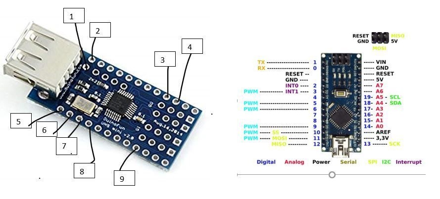
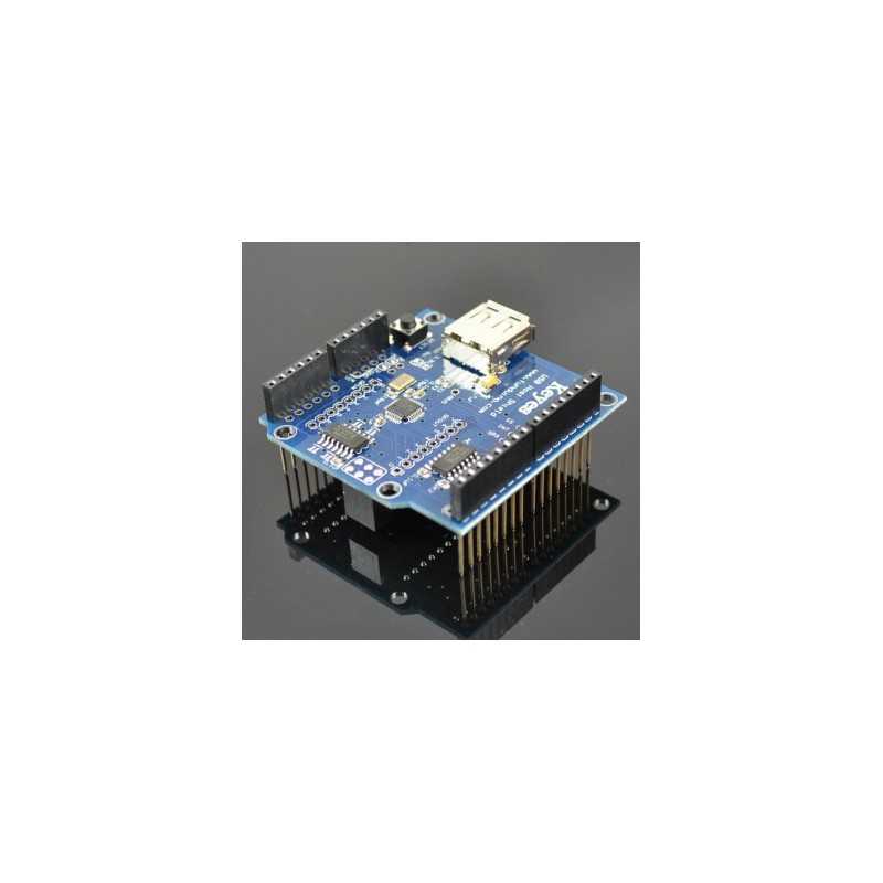
Event handler for shell connection called whenever data sent from Android to Microcontroller You can checkout the source for the Arduino sketch from Github, or just copy and paste the following into the Arduino IDE. The Arduino USB Host Shield is based on the MAX3421E which is a USB peripheral/host controller containing the digital logic and analog circuitry necessary to implement a full-speed USB peripheral or a full-/low-speed host compliant to USB specification rev 2.0. Microbridge uses Android Debug Bridge (ABD) forwarding over TCP, rather than the official Google Android ADK. The Arduino USB Host Shield allows you to connect a USB device to your Arduino board. The sketch uses the Microbridgeimplementation by Niels Brouwers. Orange Dual Dark 50 Twin Channel Guitar Head With Diy Foot Switch. Also pin 0 and 1 are used to program the Arduino, and the USB Host Shield uses pins 9-12 if Im not mistaken. You can also use other pins, but then you need to modify the examples in the library. Next, upload the Arduino sketch to the microcontroller. This Arduino sketch uses a USB Host shield to transfer preset data to one of the. The important ones are pin 7 (RTS), which I connected to digital input 2 on the Arduino, and pin 2 (RXD), which I connected to pin 3. Although it is confusing because the wording is something like for arduino uno 2560 of which there is no such thing to my knowledge. But it also says that it requires a 2560 (which is an arduino mega). Here is a diagram of the completed circuit (created with Fritzing): It clearly says in the description that it is for an arduino uno (and the photo looks like an Uno shield). The resistors, in this case, are being used to prevent current overdraw to the LEDs. The example uses digital pins 2, 3, and 4, but can be used with any IO pin that doesn’t interfere with the SPI communication with the USB Host Board. Google ADK board, Freeduino ADK board , Seeed Studio ADK board, and DIY Drones ADK boardĬonnect the 330 ohm resistors in series with the anodes of the LEDs to the desired digital output pins, and the cathodes of the LEDs to ground. This CAN-BUS Shield adopts MCP2515 CAN Bus controller with SPI interface and MCP2551 CAN transceiver to give your Arduino/Seeeduino CAN-BUS capability. It is commonly found on modern machine tools, such as an automotive diagnostic bus. I am thinking that maybe the USB data+ and data- lines might need to be swapped, but I don't know.First, make sure you have setup the development environments for Arduino and Android: CAN-BUS is a common industrial bus because of its long travel distance, medium communication speed and high reliability. I checked USB Pin 1 up on the slave so I know it's getting the 5V.)īut now, when the same firmware attempts to send some bytes over to my USB device, the TX light will not flash and nothing gets transmitted.

The firmware flashes the Digital Pin 13 LED, so I know that the firmware is running. (My Arduino board now has an external power supply to provide USB power.


My problem occurs when I disconnect my Arduino's USB cable from the PC and connect to my own USB device - a FTDI compatible USB slave. I can successfully send and receive serial data between the Arduino and the PC using the Arduino software's "Serial Monitor." The Arduino board's TX light flashes for each byte sent up to the PC.
#ARDUINO USB HOST SHIELD PIN 9 SOFTWARE#
The Software I am using is Arduino 1.0 on my PC to write, compile and upload the firmware to the Arduino board.
#ARDUINO USB HOST SHIELD PIN 9 HOW TO#
Note for any beginners out there, this nice video explains how to do Arduino serial transmission over the USB: I am using an Arduino-compatible board with USB host shield to send and receive serial data throught its USB port.


 0 kommentar(er)
